Guías Técnicas
15 mar 202620 min
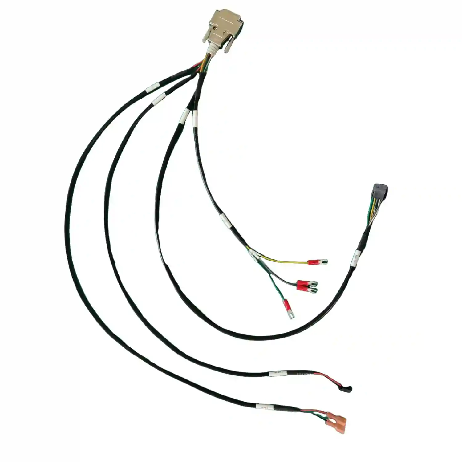
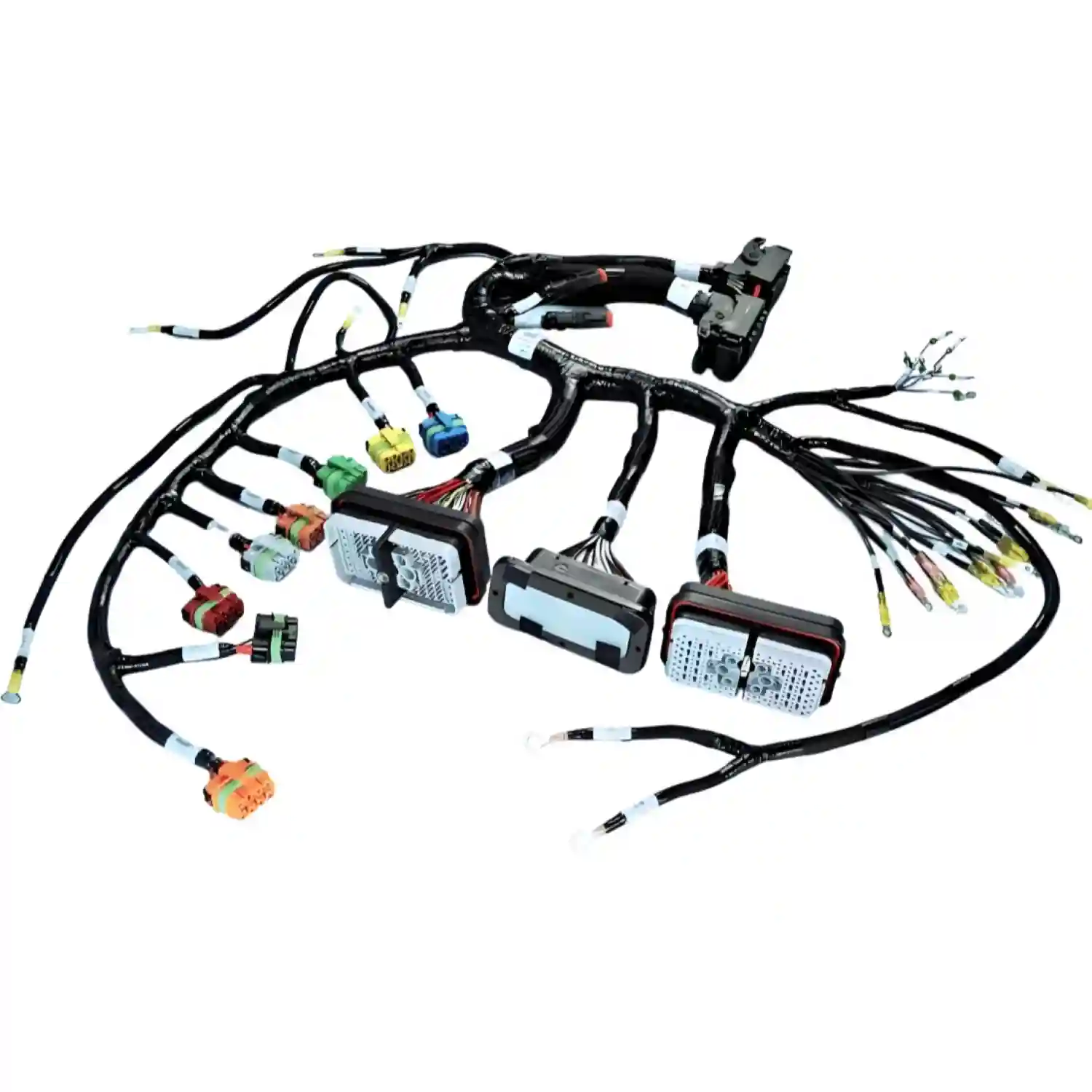
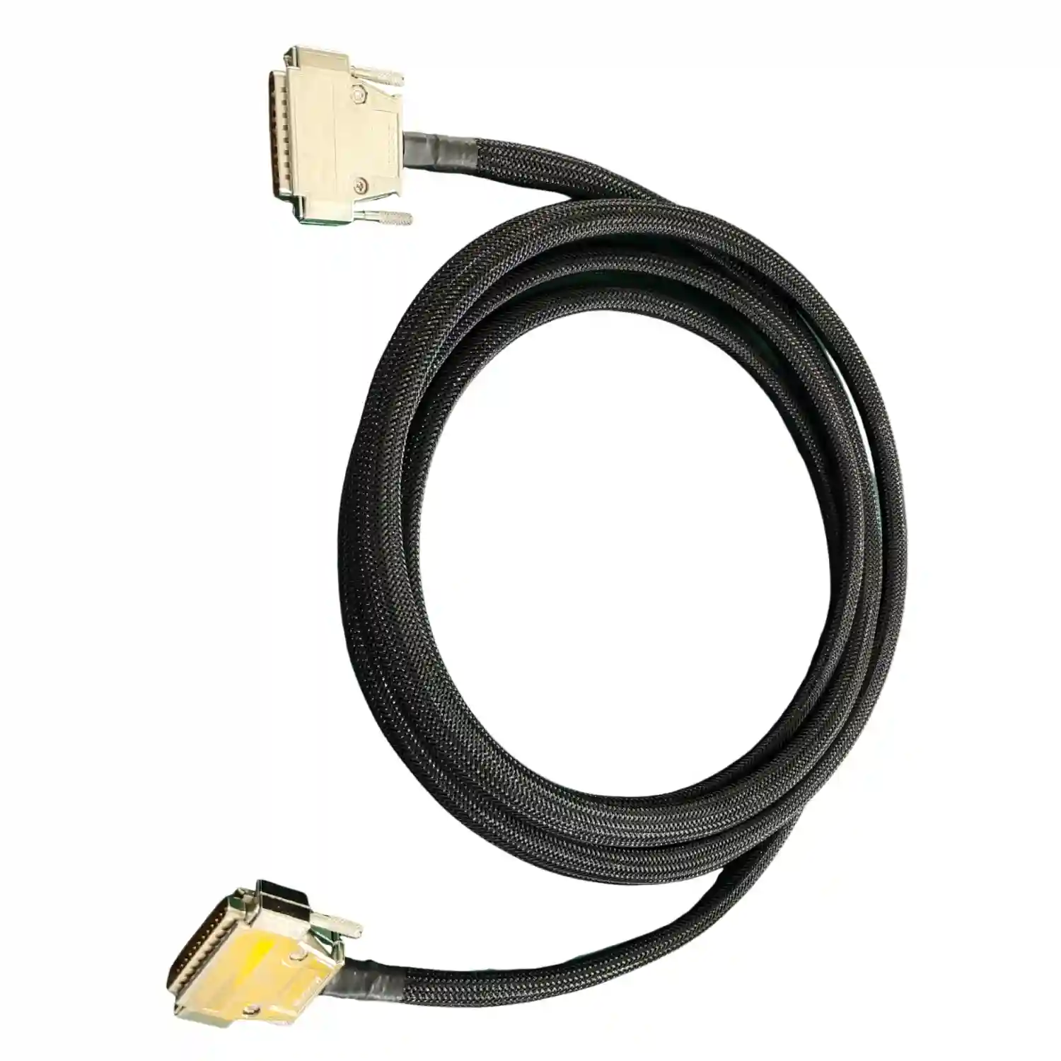
IPC 620: Guía Completa de la Norma para Arneses y Cables — Clases, Requisitos y Certificación
Guía completa sobre IPC/WHMA-A-620E: la norma de referencia para ensamblajes de arneses y cables. Clases 1, 2 y 3, criterios de crimpado, soldadura, blindaje, inspección visual y certificación. Tabla comparativa IPC 620 vs IPC 610 y checklist de cumplimiento.
IPC 620IPC/WHMA-A-620Arneses de Cables
LEER MÁS